Posts Tagged ‘Tesla’

Pyramid Sonic Transceiver Technology – Part 3

October 15, 2021

The Resonant Crowns of Khemet

Looking at the White Crown of Upper Egypt (Hedjet, hdt) indicates a technological reasoning behind it design, yes I do not think they just randomly invented it without simple reasoning and logical inclusion. As with the other crowns they all served a similar function, one of communication through logical utility and natural means. “Per Neter”, “House of Nature”, the nature of sound, light and vibrations of communion to each other and other living beings. This is understood as the longitudinal vibrations of sound and of light, each only being a multiple octave distant from each other, one medium is the Ether the other is Matter (Air, Water, Earth).

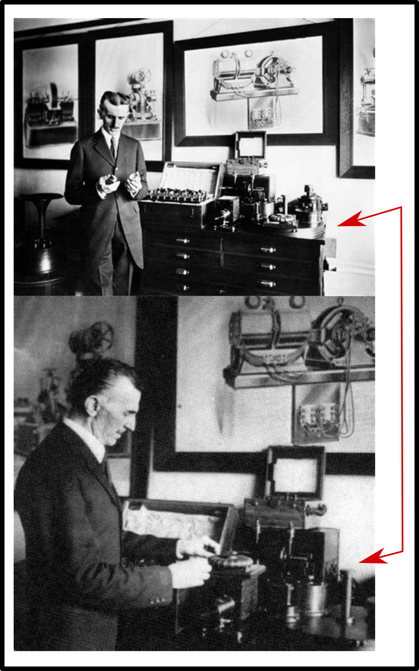
The messenger of our time who understood this “Neter” was Nikola Tesla, in the past Christiaan Huygens was a proponent of it in his time and Roger Boscovich in his time as well. Fortunately you cannot fudge the longitudinal “neter” of sound, it is all around us and our ears and voices are organs we are closely connected to. On the other hand the fake Scientism movement which began in the early part of the 20th Century, which hijacked the symbols and contorted the mathematics to be some surreal multidimensional occult scheme. We are lucky that we have had some great minds and logical thinkers who knew the false paradigm was being perpetrated onto our scientific community.

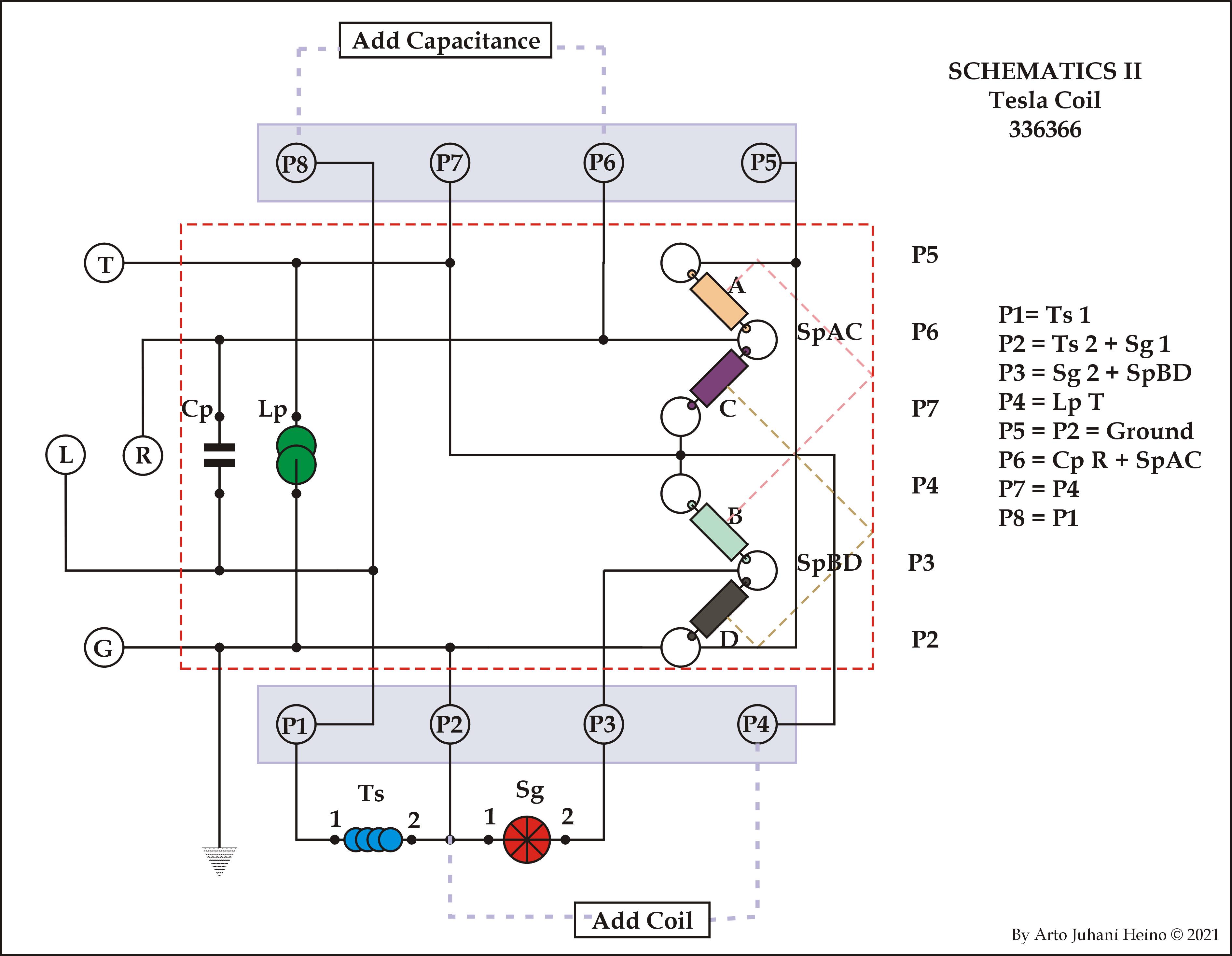
As a Musician, I could recognise the acoustic volumetric of the crown almost immediately, that being in a vocal range. After taking great care to find the measure of what constituted the Resonator, I quickly found the design concepts that was used by the Khemtians. The next step was to look if there were schematics in any wall art, as possible translations of vibrations of sound to electricity and back to sound was taking place.

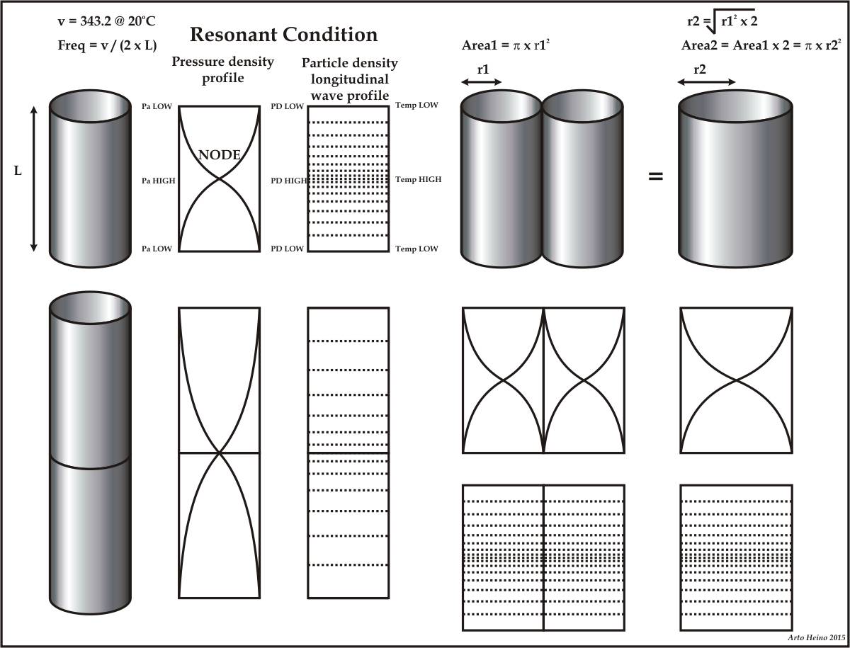
The fundamental wave length came from a careful measure using Google Earth was to reveal the base wave frequency that I should look at. After reading many volumes of Geological data regarding the Density, Bulk Modulus and Sonic Velocity of rocks of different genre, local to Egypt and other ancient sites, I can estimate the bedrock sonic velocity is usually around 5979.85 m/s, the Density about 3000 kg/vol and the Modulus is 10.7 Gpa, when translated to the Ancient measures, we have a Velocity of 80000 P per sec, a Density of about 2 Q/vol and the Modulus of about 1500. The distance from Senusret II Pyramid to The Great Pyramid is exactly 160000 Royal Cubits, simple calculations reveal that 14 seconds will transpire before your signal will be received and 28 seconds for the return signal, this could be considered a Time standard.

The Resonant frequency of the source to and from the destination = 0.0714285714 Hz

The Vocal Chord Range

= 65.714 – 4600 hz Wide Band
= 131.43 – 2044.44 hz Medium Band
= 262.857 – 920 hz Narrow Band

Male Speaking Vocal Range        = 85 – 155 hz
Female Speaking Vocal Range     = 165 – 255 hz
Children’s Speaking Vocal Range = 180 – 360 hz

The Crowns and head gear Range = 36 – 440 hz

The Wave Lengths
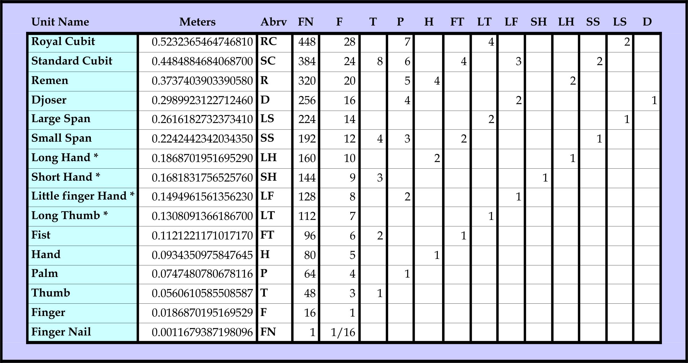
WB = 343.841/65.714 = 5.232365 mtrs = 10 RC = 280 F
= 343.841/4600 = 0.074748 mtrs = 1 P = 4 F

MB = 343.841/131.43 = 2.616194 mtrs = 5 RC = 140 F
= 343.841/2044.44 = 0.168183 mtrs = 1 SH = 9 F

NB = 343.841/262.857 = 1.308091 mtrs = 5 LS = 70 F
= 343.841/920 = 0.373740 mtrs = 1 D = 16 F

The design of the Hedjet Crown was a well drawn out study, I referred to many icons that show clear pictures, the first being the Narma Palette and many beautiful sculptures and large statues. It seems to have a slightly different size depending on the region and the Dynasty that had created the artwork. So instead of slavishly copying something that we had no sample of, with only diagrams or sculptured versions, I went with the most direct method, think like an Ancient and design like an artist of the time and build like an engineer of Khemet. As the Royal Cubit was the fundamental rule that all these ancient wonders that were created, I used my perfected measure of 1 RC (523.2365mm) as the foundation of design and engineering, also being 28 fingers (18.687mm), where I could use the finger as the smallest measure.

The large curvature of the circle D3 of the Hedjet is 4 RC, I could have chose 3 RC but the cavity would have been too small and the curve too tight, also if it was 5 RC the crown would have been to tall, 4 RC was the best fit that also matched the edge of D4, which is 12 F or 1 Small Span. The A1 dimension of 2 F was not a hard choice, it lined up to most crowns and was easy to pick, whereas the body had to be dissected to cylinders to get an approximate volume, using a basic form of calculus and the Egyptian measure I achieved a simple design tool that could be used on many semi-organic designs. The inside of the Hedjet could be two chambers or more, in line with the design of the cochlea, when unwound has two basic chambers, this could indicate a slightly modified version of my interpretation, which I will express in another design.

My intuition told me that I would arrive at a tonal resonance around the vocal region, being 95 Hz it was just about right for the low end of a set of large male vocal chords. The measure was the key, whole numbers of Fingers is the how we can design natural machines, like a resonator. The DNA understands these forms, your ears and your vocal chords are the result of this understanding, how can we imagine these were randomly adapted, they were designed by a master architect of the universe, we can only imitate its great design.

Here is is short list of Gems used by the Ancient Egyptians (PZ is the preferred piezo ):

Tourmaline Blue PZ
Amethyst Purple PZ
Sapphire PZ
Emerald PZ
Ruby PZ
Diamond PZ
Garnet Red
Lapis Lazuli Blue
Obsidian grey
Carnelian Orange
Jasper Orange
Turquoise Blue
Carnelian

All the crowns have the basic form of an acoustic device of some sort, this was their unique mastery of this most ancient technology and science, Tourmaline was the first choice for the Piezo crystal, this was one of the regular stones used in Egyptian jewellery and art.

Sound Refraction

The focal length of a spherical lens (measured from the surface of the lens to the focal point) is given by focal length sphere where r is the radius of the sphere, m1 is index of refraction of the surrounding medium and m2 is the index of refraction of the lens material.

r = Radius of Sphere
m1 = Index of refraction of surrounding medium
m2 = Index of refraction of the lens material
v1 = Velocity of Sound of surrounding medium
v2 = Velocity of sound of the lens material
f = Focal length from the surface of sphere to the Focal point

f = r*(2-m2/m1)/2*(m2/m2-1)
f = r*(2-v1/v2)/2*(v1/v2-1)

If the lens material has a greater velocity then it becomes a convergent lens and if it is less that it is a divergent lens.

Zp = Acoustic Impedance Piezo Electric Material
Zl = Acoustic Impedance of Loading Material
Wm = Matching Material Layer Wavelength

Best impedance match:

Wm/4 = Zm

Impedance of matching layer material is:

Zm = (Zp x Zl)^(1/2)

Wide band acoustic impedance:

Zm = (Zp x Zl^2)^(1/3)

Improving acoustic matching:

Zm1 = (Zp^4 x Zl^3)^(1/3)
Zm2 = (Zp x Zl^6)*(1/7)

Mixing powdered piezo materials with hard resins and creating a polymer is one way of fabricating matching layers.
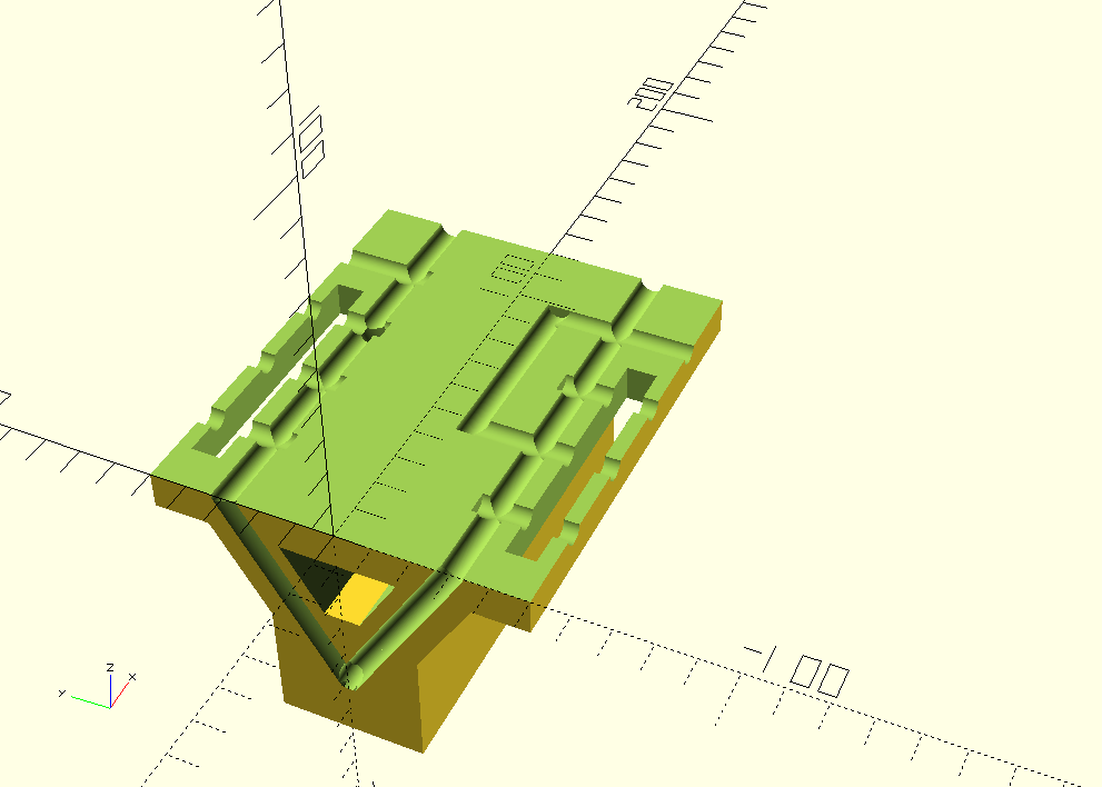
Hedjet Crown

This was the first I had seen that would work acoustically, using the Helmholtz resonator as the basic design to follow. The volumes are best approximated as the chambers are narrow band devices and not just singular tone, The narrow band fits the voice well, my criteria was to use it like a musical instrument, where pure tones resonate distinctly, a vibration from an external source being simple not highly modulated, one from the vibrations of a staff or device that has a limited tonal range. The connections to the circuit and ears are not included, these would be more decorative and need to be adjusted for the head of the user. The main chamber could be split in two, as per the uncoiled cochlea. I chose the size in accordance to the Royal Cubit as the standard, by it having direction relationship to the Longitudinal velocity of light. The original crown was worn by Narmer and he was a giant, so I figured this was the most suitable size, as I noticed the Hedjet sometimes seemed over size when the king was not as big in many wall carving. Later Hedjets could have been smaller, making the frequencies much higher than 95Hz.
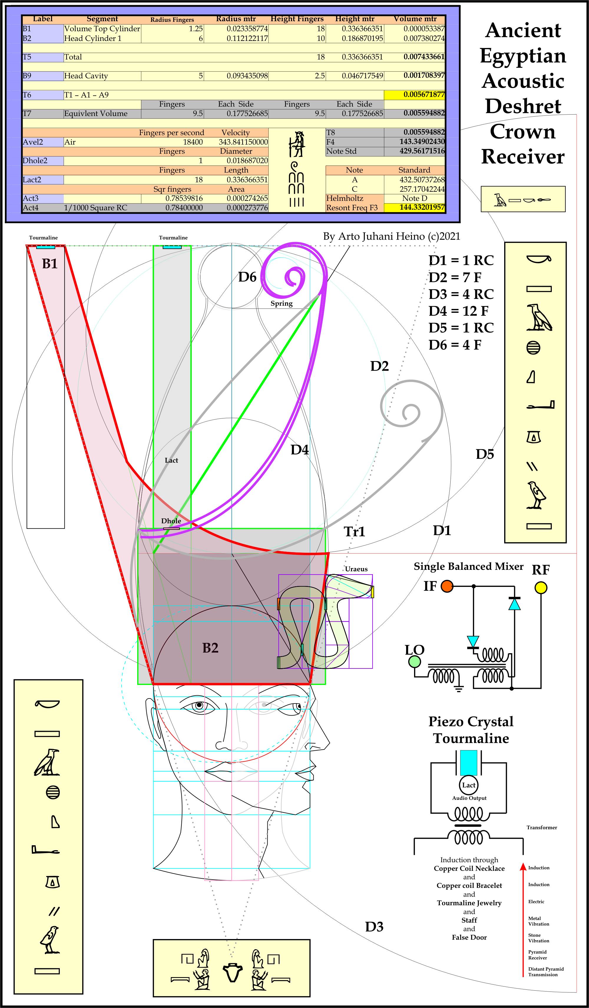
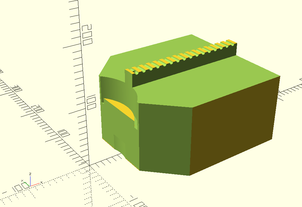
acousticrown3c.

Deshret Crown

This one was simple once I found the first crowns acoustic design logic. The spiral piece could be a hollow chamber as well, making it look like the cochlea, where adjustments to the tone and frequency could be made or even a direct contact to another acoustic vessel. The Green outlined section is the simplified version of the crown volumes that makes the mathematics much simpler. Tr1 is a golden triangle that was found after I had almost drawn the whole unit, it points to the heart, the size is 471/18 x 818/18 fingers = 488,977mm x 849.221mm. The Uraeus I put on the crown is mainly to show its location and design elements, the scale is not correct, it would be at least 1/2 to 3/4 of the size I have drawn.

AcoustiCrownLN1b.

Hathors Head Gear

This was a simple progression, now using the symbolic shapes of the sun disk and horns to create the necessary configurations. The C2 chamber in green is an approximation of the neck of the horn resonators. The P5, P6 and P7 are other positions the Piezo crystal could be placed and change how the horn chambers worked harmonically. The P6 is also connected to the main chamber, so a feedback will occur. The P7 connection is used when you use both horns, what you will get is one horn in compression while the other horn is in expansion, as opposite phases. P5 will drive the side horn but will also have a short wave of 1/7nth the of the wave length of the horn, thus giving you a complex sound wave. Tr2 is another golden triangle that I discovered after drawing most of the head gear, it points to the mouth, the size is 18.2 x 28 Fingers(1 RC).

AcoustiCrownLT1a.

Other Crowns and Head Gear

After intuitive generating these designs, I could see every crown and head gear designs were connected to the cochlea and other sound chambers. The feathered version of the Hedjet called the Atef Crown makes me consider that the internals as two chambers and the feathers as ticklers for a variety of harmonics. Amun crown has two distinct chambers, and it’s appearance is significantly like a straightened out cochlea. The Shuti Crown has spiral chambers(rams horns) which would be a shorter version than long straight chambers. The blue Khepresh Crown is much shorter and has a chamber as well, while the Cap crown has even a smaller chamber,

Each crown or head gear or combinations seems to indicate a narrow band of frequencies and could possibly be that each has a function of communication at those frequencies, where the deployment of signals were directed to those who wore a specific crowns or hats in a region. What I could gather by the wonderful hieroglyphs is that stock holdings were relayed among the Khemtian empire using false doors as exchanges with a schedule using specific times by officials with certain hats, which were regulated in a religious fashion to keep the communication channels linked up. The pyramids served to create, amplify and relay the complete network of acoustic signals around the empire.

The transmission of signals via a sonic device inside the sarcophagus like I have previously described would be linked to the regular acoustic carrier pyramid frequencies, with the use of a Sistrum as the calling ring when pressed against the walls in certain locations, like the false doors, when done at regular intervals to indicate a transmission signal.

FalseDoor111a

The Uraeus is a 1 1/2 or 3/2 wave system, the locations of the Piezo crystal help with feedback tuning and aerial reception of Sonic frequencies, these would be coupled to the main acoustic chamber and also act like the diode mixer in radio when separating frequencies to be decoded. By the design it looks like a single balanced mixer, where the RF (Radio frequencies) is the Sonic wave and the LO (Low frequencies) is the voice and the IF (intermediate frequencies) are the carrier frequencies.

As this is still a working document, excuse any errors or omissions, but if you found this work of value please donate to keep this and other projects alive. regards Arto

One-Time
Monthly
Yearly

Make a one-time donation

Make a monthly donation

Make a yearly donation

Choose an amount

¤5.00
¤15.00
¤100.00
¤5.00
¤15.00
¤100.00
¤5.00
¤15.00
¤100.00

Or enter a custom amount


Your contribution is appreciated.

Your contribution is appreciated.

Your contribution is appreciated.

DonateDonate monthlyDonate yearly

The Pyramid Sonic Transceiver Technology

September 18, 2021

Ancient Royal Cubit and How a Pyramid Works

(This is a draft of part of the Archaeology chapter, so please excuse incomplete data and any errors)

When studied and looked at from one view of the ancient Egyptian measure, it has so many variants, that it makes you wonder, what was reasoning behind the differences? The main stream Archaeologists never delved into any logic or reason and discounted it as just poor standards that had no relevance to an exact science, while only being a measure of ones arm, hand or finger.

After many years of thought I concluded, that the original pyramids and the many fine stone objects inside them were the remnants of the true science of the Kemetians but not fully understood by the Dynastic Egyptians, they seem to have forgotten some parts of the ancient technology, it became a ritual, the remaining shell of its true intentions, it was stylised. In my last volume I elucidated the Royal Cubit as the unit for the measure of the Longitudinal velocity of Light.

This was the start, as we now had a clean beginning with a absolute measure of 900000000 Royal Cubits. As you can see by the diagram, the number of waves are always the same, the type of medium is what causes the measure to change. This methodology can account for the variant sizes, the Illhan sarcophagus measure shows that Ozone was the medium inside the pyramid, as this is the dielectric that will give you the correct Royal Cubit measure for the internals.

The Pyramid complex is a machine that uses stone both as a dielectric in the higher frequencies and as an audio conduit in the mid frequencies through the stone with coupling with the lower Earth frequencies in the cavities filled with a gaseous or liquid medium. The contents of the sarcophagus should be filled with structures that emit frequencies that resonate with the structure , these are materials that could be radiation emitters. Most gem stones are emitters of radiation, with elements like cobalt, boron, uranium, potassium, much of these are in a natural state all around us, these appear as the offerings required to keep the machine running, it was ritualised over time. The atmosphere inside the sarcophagus and the tombs will become ionised, thus changing the permittivity of the gas, also allowing the conductivity to increase, this will drive a differential heat engine, that have audio and plasma acoustics to have two nodes, each will be charged with different polarities , hot = +, cold = -, as per an electrical generator. This now becomes a natural electrical charge accumulator, that drives a cavity shock wave generator that creates a current of electricity. The pyramids cavities reveal a Thermo-Acoustic plasma engine. The mud-brick layer on many Pyramids acted like an energy reservoir and a acoustic baffle, Pyramids acted like motors, generators and accumulators, where some were passive in their functions.

The addition of frequencies inside the sonic wave, due to each material being of different permittivity, permeability, EM refractive index and mass density, impedance to electricity and to the acoustic properties will give you the velocity of energy transfer in, on and through the material. This velocity can be used to dissipate the heat loss through the crystal lattice as you lower the frequency by the impedance, both electrically and with sonics. This will give you a differential of temperature at either extreme interface, thus the sonic created and maintained by heat, can be recoverable back to electricity by a engineered Peltier layer of materials or other means. No moving parts, the initial impulse is an amplified Earth sonic that is always present as 8 hz in the atmosphere and 12 hz in the Earth and its low sub harmonics.

A pyramid is the earth frequency reflector to a focal point, the many rooms and corridors are carefully designed, as a acoustic receiver, in the lower frequencies. The reason they are so big, is that the sound it captures is directed at the correct angle to the acoustic antenna system, where the acoustic channel drive a sound in high resonance and activates the differential heat engine.

The sarcophagus can now be the focal area of transmission or/and reception, as this diagram(next blog) shows the different sound modes inside the sarcophagus. You can articulate these by frequency adjustment by an acoustic lens and other means inside the box, which is inside the tomb and inside the pyramids sub structure. This type of pyramid is of interest as it is easier to understand, we must walk before we run. Pyramids as functioning machines, is not a common subject in any library, so we will start here.

The scheme of measure used by the engineers of Kemet was Royal Cubits, Standard Cubits, Hands. Palms and Fingers. The use of these divisions of metrology will be clear when you work out the sonic of materials and how they work together. The scheme of layout and cross sectional designs were purely a work of the ancient genius that understood vibrational technology and the natural environment. The machines were built from stone connected to the bedrock and only had the smallest components crafted from metals and dielectrics.

Let us look at a few simple but hidden knowledge of the the measures used by the Kemets.

Longitudinal Velocity of Light( light x pi/2) =9000000000 Royal Cubits per Second

470912789.827213 / 9000000000 = 0.523236546474681 meters

This will give you the Length of a Royal Cubit = 1 Royal Cubit

1 Palm = Royal Cubit / 7 = 4 F = 0.0747480780678116 mtrs

1 Hand = Royal Cubit / 5.6 = 5 F = 0.0934350975847645 mtrs

1 Finger = Royal Cubit / 28 = 0.0186870195169529 mtrs

__________________________________________________________

Using C = 299301329.866211 ms as Light Velocity(per Illhan)

The velocity of Sound in Air (344 m/s velocity at 22 deg C)

344.40553733326 / 0.0748707073333 =4600 Palms per second

___________________________________________________________

Using C = 299792458 ms as Light Velocity

The velocity of Sound in Air (343.843 m/s velocity at 21.075 deg C)

343.84342857142 / 0.0747485714285 =4600 Palms per second

The velocity of Sound in the Bedrock (5989.6586 m/s velocity)(Illhan)

5989.658666666 / 0.0748707073333 =80000 Palms per second

____________________________________________________________

The Wavelength of Hydrogen (EMF from the Universe= 1420405751.768 hz)

Meters = 0.211061140538923

Royal Cubit used = 0.527652851347307

Velocity profile of RC used = 297283280.062913 mtrs/sec

Royal Cubit/ 2.5 = 0.4 RC = 0.211061140538923 mtrs

2.8 Hands = 11.2 Fingers = 1 Elbow to Wrist (EW)

_____________________________________________________________

The Density of a Stone used in a design

2452.02927295 = Mass / Volume = Kilogram/Mtr3

1/1.715 CF = 0.58309038 = Volume of 1 Qedet in Cubic Fingers

1.715 Qedets = 1 Cubic Fingers x Density

1 / (1/1.715) = 1.715 = Density in Q/CF

49320584224.971 = Modulus Of the stone in SI units

______________________________________________________________

The Modulus in Qedets and Palms per second

600000 PS = 4484.8846840687 mtrs per sec Velocity of Stone

1.715 x 600000^2 = Density x Velocity^2 in Qedets and Palms per sec

6174000000 QPS2 = 6174000000 / 9000000 = 686 M *

So we have the velocity, density, mass, volume and modulus of the stone that we need to use to build or to transmit and receive vibrations. We can use geometry to adjust all the parameters to create acoustic lenses or direct the vibrations to a focus point for interpretation using some form of acoustic technology.

1 Palm = 0.074748078068 mtrs

1 Cubic Finger = 0.0000065255950149 cubic mtrs

1 Qedet = 0.00933 kg (Flinders Petrie)

Density = Mass / Volume

Mass = Density x Volume

Volume = Mass / Density

How I derived some of these values, it will be easier to understand as I show you the data I have accumulated by the study of all the pyramids.

So how do we start to form a communication channels and power generation from geometry, stone, acoustics, plasma and resonant heat channels. We must start with the geometric means, where the stone amplifiers with stone antennas must be built into the bedrock, where sonic vibrations can activate.

There are a few equations that will help in this design process, let us inspect the communication between two pyramids. I discovered the the distance between Senurset II (sewaset)and Giza to be is exactly 160000 royal cubits. This was one of the clues that has led me to this clear knowledge.

Distance = 160000 Royal Cubits = 1120000 Palms

Velocity of Sound in Bedrock = 80000 Palms per second

Time =D / v = 112000/80000 = 14 seconds

Frequency = 1/ time = F = 0.0714285714 hz = D (A= 438.36184192 hz)

Lowest Piano D = F *1024 = 73.142857138 Hz

The wave length inside the tomb = 4 Royal Cubits = 28 palms

So it looks like we could use octaves of “D” to make a communication channel between Senurset II and Giza.

Test case #1

Velocity profile of Limestone 0% porosity = 6813.236733 mtrs per sec

As Royal cubits = 13000 RC per sec

Velocity profile of Limestone 10% porosity = 5109.92755 mtrs per sec

As Royal cubits = 9750 RC per sec

Velocity profile of Limestone 20% porosity = 4087.94204 mtrs per sec

As Royal Cubits = 7800 RC per sec

Velocity profile of Limestone 30% porosity = 3406.61836 mtrs per sec

As Royal Cubits = 6500 RC per sec

In a Test Case above we have 4 different Velocity profiles, this seems innocuous, until you compare it to the 0% porosity, here are the figures:

13000/13000 = 1 = 0 % porosity

13000/9750 = 1 1/3 = 10 % porosity

13000/7800 = 1 2/3 = 20 % porosity

13000/6500 = 2 = 30 % porosity

These are musical and concordant frequencies. When the whole gamut of limestone, red granite and many other stones are put into the correct context, lined up with density, velocity, modulus, porosity, dielectric, permeability and impedance are factored and aligned to resonances with harmonic content, you will not see the true nature of the Pyramids.

This understanding is clear that their intentions was to resonate stone and air, creating communications and energy transfer, this is of a past technology that lay hidden in the Kemetian engineering. When you look at the all the concordant data you will see the science of ancient Egypt, they had a science not just a geomatra of holy numbers , worship of idols and Gods.

The Dynastic Egyptians had lost much of the ancient knowledge after the flood destroyed most of the Ancient world, many of the machines stopped functioning, maybe Giza was still running, it was after all the main trigger for all network of ground longitudinal waves, both electrical and acoustic between all the pyramids. The survivors may have had some technology left, but the link to the priests of that knowledge were gone, they developed a philosophy aligned to the downward spiral of mankind, just as the Yuga cycle was nearing it nadir, all the knowledge to read the language vanished. The Egyptians called it the underworld, the lost dark chasms of mankind, where memory of our past gets destroyed, misaligned and lost.

Measure and Metrology

We need to try and recover what was lost in the engineering of the pyramids, by means of the actual objects and structures left behind. Much of what I have looked at was already found by Petries and he did a wonderful job of recording his findings. I will list my own interpretations along side the what has been found and measured. I will start with the Royal Cubit, as the standard, it this seems to be the most scientifically defined unit that I have been able to decipher, in all of Egypt. Do not forget that this is the unperturbed unit, not the regular measure as noted by my earlier iterations regarding the dielectric as the change in length. So here are the first list to define the length to meters, so we can relate it to modern understanding.

* New Names and Lengths based on conjecture.

So the base length by historic discovery is the Finger, this makes the building of a Metrology system easier. Here are the divisions of lengths according to written and measured discovery, with a few added “ * ” to indicate new sizes. The requirements of building is the volume standard, then the mass and the density considerations. This list is based on 1 Cubic Finger as the smallest usable unit.

Now that we have established a system based of 16 different unit measures, we must now move to weights, mass and density to complete our approach to the transmission and building process.

These volumetrics are already useful in liquid measurement, such as the equivalent in litres or gallons. This will not enough to create a technology, the Density of the materials plays a major role, this can be done with a set of scales and a ruler.

The Qedet is a weight that was used in much of ancient Egypt, this was a found by Petrie to be about 9.33 grams, a size of it was also noted. I simplified the size and cubed the sides to arrive at 1.715 Qedets = 1 Cubic Finger with a Density of about 2452.03 which can be found by making a standard that it can be checked against. Other densities can be found by comparing volumes against the mass using a scale.

Now that we have some clue on how to proceed, I have found many interesting unit values that pop out when crossing over to the ancient units.

Here is a quad set of figures that show some very musical values, when you add a suitable length to create the required fundamental tone in the material.

In Ancient units:

Name – Material – Density – Velocity – Modulus

Set – Stone – Q/CF – P per sec -Den x Vel^2/9000000

Set A – Sand – 1 – 30000 -100

Set B – Granite -1 143/200 – 57000 – 686

Set C – Dolerite – 2 – 60000 – 722

Set D – Basalt – 2 34/343 – 80000 – 1492 244/343

_________________________________________________________

Now in SI units:

Name – Material – Density – Velocity – Modulus

Set – Stone -Kg/m3 – mtr per sec – Den x Vel^2

Set A – Sands -1429.754678 – 2242.442 – 7189589537.171

Set B – Granite – 2452.03 – 4484.884 – 49320584224.971

Set C – Dolomite – 2859.509 – 4260.64 – 51908836458.377

Set D – Basalt – 3001.2343 – 5979.846 – 107319820496.616

As you can see the ancient units are much more unified and much easier to remember and calculate with.

The rest of the unfinished chapter will include the acoustic map of all the pyramid sonic fields, with frequencies and the inclusion of some of the devices inside the sarcophagus and sonic translator devices. I had to reinvent all the parts from some of the artefacts I have seen in the museums. I will add some schematics of these machines in the next blog, if all goes well I will be able to test these in a small scale, if resources are available. Regards Arto

One-Time
Monthly
Yearly

If you would like to help my efforts in my future posts, I would very much appreciate your donation.

Make a monthly donation

Make a yearly donation

Choose an amount

A$5.00
A$15.00
A$100.00
A$5.00
A$15.00
A$100.00
A$5.00
A$15.00
A$100.00

Or enter a custom amount

A$

Your contribution is appreciated.

Your contribution is appreciated.

Your contribution is appreciated.

DonateDonate monthlyDonate yearly

Tesla Coil 336366 – Part 2

April 8, 2021

I forgot to add this vital understanding of volume and surface area regarding Tesla coils.

First you must realise that Tesla placed a high premium on getting the resonant factors correct. That any amount of electricity has a definite number (be coulombs or esu or ?) and must be included in the overall design structure. When the resonant action has been instigated there is a transference of magnetic to electrostatic potentials and visa versa, this must be balanced and carefully considered. The impedance matching is of vital importance to this action but a secondary balance is the volumes and areas of each set of coils.

The exact parameters can be calculated and you can see by Tesla’s work in Colorado Springs, he realised that a short cylindrical coil can be better utilised than a long coil and a flat spiral is much more compact than any cylinder can be. These studies had revealed to Tesla a beautiful geometric design that cannot be improved any further, a very compact and portable unit that awaits a audience that has chosen to ignore his proclamations. Below is the coil I am talking about.

I have drawn up such a coil system, approx 400mm x 400mm x 200mm unit (approx), it unfolds and plugs into a power source (Tesla AC) and hopefully communicates to a clone at a preset short distance with losses. Not only voice/data but Energy as well (100 watts or so). The frequency was always too high to be of use in power transfer as the losses increased with the frequency.

Below are listed only my estimates by reading much data and personal experience.

System…………………………………….Waste.to.radiation………Power.Delivery

Tesla system (no compromise).1 to 5…………………………..95 to 99

Radio system…………………………….99.9 to 100 0………………1 to 0.00001

High freq Tesla Flat……………………40……………………………….60

High freq Tesla Cyl……………………..60………………………………40

Low freq Tesla Flat…………………….15……………………………….85

Low freq Tesla Cyl……………………..30……………………………….70

So why did I design 336366 coil system using a traditional long cylinder? Simple, convenience and to prove to myself that the longitudinal velocity is the KEY to instant communication as Tesla suggested. Efficiency was not always the driving factor but the ease of material supply and a personal demand for longer wave lengths in a simple setup. The flat coil size became problematic in many ways, still I will go down that road again.

Coil…………………………………………………………..Volume and Area

Volume of Secondary………………………………0.0004 Cubic Mtrs

Surface Area of Secondary………………………0.796 Sqr Mtrs

MAX Volume of Primary…………………………..0.00068 Cubic Mtrs

MIN Volume of Primary……………………………0.000016 Cubic Mtrs

MAX Surface Area of Primary…………………..0.424 Sqr Mtrs

MIN Surface Area of Primary……………………0.01 Sqr Mtrs

Primary Volume at the design size…………..0.00045 Cubic Mtrs

Primary Surface Area at the design size…..0.285 Cubic Mtrs

What Turn…………………………………………………..14

What Area Secondary to Primary Equiv……..0.78 Sqr Mtrs

What Turn (beyond this design)…………………26

What Volume Secondary to Primary Equiv…0.0004 Cubic Mtrs

What Turn (very close )…………………………….13

I want to follow up with the real McCoy, in the not too distance future, regards Arto.

Tesla Coil 336366

March 26, 2021

As this is part of my chapter on Tesla Coils, I might as well fill you in. I had recently consumed something that affected my stomach, not pleasant, it gave me an ulcer. So while I was recovering, with natural remedies, I decided try to finish one of my Tesla Coil designs.

I have been tentatively working on this Tesla Coil project for a few years(8 lol), specifically for Transmitting and Receiving, using 700 mtrs as a distance that needs to be crossed or a multiple of this, 1400, 2100, 2800 etc.

I figured that building from standard parts with a simple STL 3D prints with an accurate dimensional scheme we should get frequency matching accuracy due to the uniformity of the build.

Here is a TXT file, which is a couple of SCAD programs, that I have been translating my Tesla Coil Data to make a jig I can 3D print and put the main components of the Tesla Coil into a simple assemblage with some 3D parts.

1 x 1000mm of 110 tube
1 x 150/110 base connector
1 x 350 + mtrs of AWG 21 wire
1 x 16 mtrs of 1/4 copper tube
1 x 3Dcoil BaseL STL
1 x 3Dcoil BaseR STL
2 x 3Dcoil Base/edge Connector STL
1 x 100mm ball (Al, Cu) or (STL + Al foil)
1 x 4 point Switch Configuration Adapter STL
1 x 240v/15000v 60 ma Transformer
1 x Rotary Spark Gap 8″ dim + 12 protrusions at 400 RPM, makes 80 BPS
1 x Safety anti kick back system (protecting Mains & transformer)

Inductance of the Primary Coil will be from-
0.376 uH to 150.25 uH
I tap mine at 14.17386 turns which gives me
67.846873 uH
Capacitance for Primary Coil:
0.0033 uF
Voltage across Cap (max 30000):
21210 volts
Secondary DC resistance:

14.6647 Ohms

I chose:

Frequency = 336366.3513 hz
110 mm tube x 800 mm length of winding of secondary coil = 350 mtrs
The wave Length of The Longitudinal wave is different to EM wave
if
WL = V1 / ( Lw x 4 ) = 1400 mtrs
or
WL = V2 / F1 = 1400 mtrs

Consider an explosion, the shock wave is the longitudinal wave and the matter with splintered bits and fire is the transverse wave. Electricity has the same properties.

I use these formulae:

Ls = Secondary Coil Inductance
Lt = Secondary Coil Stray inductances + added adapter unit
Lst = Total inductance of Secondary Coil
Cs = Secondary Capacitance of Coil
Ct = Top Capacitance + stray Caps
Cst = Total Capacitance of Secondary Coil

Lp = Primary Coil Inductance
Lq = Primary Coil Stray inductances
Lpq = Total Inductance of Primary Coil
Cp = Primary Capacitance
Cq = Stray Capacitances of coil + adjuster
Cpq = Total Capacitance for the Primary coil

V1 = Electro Magnetic (Transverse Magnetic) Light Velocity (lagging)
V1 = 299792456
V1 = (Lw / 0.52324)^3 approx
V2 = Magneto Electric (Longitudinal Electrostatic) Velocity (leading)
V2 = V1 x pi / 2
V2 = 470912891.8272
V2 = 900000000 x 1 royal cubit (0.52324 mtrs)

  • note the different phase relationships between Voltage(electrostatics) and Amperage(magnetics) when you consider Power.
  • The Electrostatic Velocity leads Electromagnetism by pi/2. The only reason resonance occurs is the exchange from inner volume electro-magnetics running at Light velocity to outer surface electrostatics running at pi/2 times this, which is still proportional to the same amount of Energy. But the velocity is out by pi/2, allowing the circuit to breath.

E = 1/2 x (Cpq x Vp^2) = 0.5 x (0.00330 uF x 0.000001) x (21210 volts)^2
E = 1/2 x (Lpq x Ip^2) = 0.5 x (67.8468 uH x 0.000001) x (147.917 amps)^2
E = 1/2 x (Cst x Vs^2) = 0.5 x (15.5688 pf x 0.00000000001) x (308785 volts)^2
E = 1/2 x (Lst x Is^2) = 0.5 x (0.01438 H) x (10.16 Amps)^2
E = 0,74222 Joules
E = W * t

WL = Wave Length
Lw = Wire Length (I use 350 mtrs)

F1 = 1 / ( 2 x pi x sqrt( Lst x Cst )
F2 = 1 / ( 2 x pi x sqrt( Lpq x Cpq )
F3 = V2 / WL
F4 = (V1 / ( Lw x 4 )) x pi / 2
F5 = (V1 / WL ) x pi / 2
F6 = V2 / ( Lw x 4 )

WL = V2 / F1
V2 = V1 x pi / 2

Lst = Ls + Lt
Cst = Cs + Ct
Lpq = Lp + Lq
Cpq = Cp + Cq

These are the requirements

F1 = F2 = F3 = F4 = F5 = F6
and
WL = Lw x 4
and
Lst x Cst = Lpq x Cpq

Primary Coil Parametrics

Inductance per turn:
1 = 0.370488 uH
2 = 1.363580
3 = 2.918217
4 = 5.038095
5 = 7.750477
6 = 11.092889
7 = 15.107919
8 = 19.840884
9 = 25.338680
10 = 31.649171
11 = 38.820833
12` = 46.902557
13 = 55.943511
14 = 65.993060 14.17386 = 67.846855 uH
15 = 77.100714
16 = 89.316083
17 = 102.688860
18 = 117.268792
19 = 133.105676
20 = 150.249344

Q = XL / R
Q = 30000 / 15
My calculations show a secondary maximum Q of about 2000
Across my cap about 20000 volts
Q x V = 40,000,000 volts

Diagrams

The way I envisaged to switch over the 2 base Tesla designs was to just plug a unit into the side of the Tesla Coil Structure and it would be a matter of pulling a lever of setting a key switch to run in either mode.

I incorporated the Capacitance cavities so you could add more later, as you see by the ports P8 and P6 are their for that reason. P2 and P4 are there if you need to reduce your inductance by any degree by paralleling another wound inductor on a metal former. These ports allow you to experiment and modify as needed.

The main point of the Adaper unit was to make it as simple as plugging your HV-Transformer and Spark Gap into a simple 1/4″ set of bolts. Follow the instructions and all will work as planned.

I have drawn three different schematics, so you can see the simple logic I used for expansion into the real world by geometric means. The design of the two triangles was so the inductance is reduced by it opposing parallels.

My Thoughts

This is only theoretical but clearly plausible if air break down is not an issue while only on on minimum idle, the loaded system when doing work will reduce safely to about 300,000 volts and less.

Next Stage

The next part of the project will be setting up a transceiver system that can exchange energy between two points 700 mtrs apart, also at 700 times the number of wave lengths, losses must be calculated by trial and error. I am guessing safely over rough terrain about 4.9 km with acceptable losses (note – grid harmonics).

Speculation

When needed, you can relay a transmission to further distances if the original signal degrades too far. You could possibly relay the Energy in Solar collectors that runs the Tesla coil and transmit it around the world, as the Earth spins, as the other relays they will start up the energy cycle again, then relay it to the next one. A continuous energy loop that is harnessing the Sun 24 hours a day. No wires, you would need 360 of these at 1 degree intervals, which is about 111 kms apart. This distance is no issue to a large well made Tesla Transmitter.

I hope you enjoy reading about this project I am still working on, regards Arto.

By the way here is the SCAD files, incomplete as yet, I will add it HERE later.

The Induction Computer Part 4

October 17, 2017

The Induction Computer Part 4

by Arto Juhani Heino (c) 2017

I am back from the wilderness, the experiences of Spring has overwhelmed my Audio and Visual organs, natures beauty is beyond any simple description. The last post I never mentioned the Trinary system that took my designs closer to a complete new type of thinking to develop a Trinary ALU, much more interesting than the Binary approach. Here is the 555 timer I promised from the last post, it is closer to a build-able relay design than my first prototype.

I didn’t show any parameters for the Basic Logic Cell. Here is my sizes and reasoning:

The Basic Logic Cell – Logical Unit

Working from the true measure the Royal Cubit approx 523.24mm, rounding to 525mm. The Palm is four fingers and seven palms make the Royal Cubit.

75mm x 75mm Sqr (aprox 3″ x 3 “)= 1 square Palm.
18.75mm Thick(rounding to 19mm, aprox 3/4” ) = 1 finger thick.

This was why I chose the Ancient Royal Cubit, when you measure the longitudinal velocity of light in royal cubits equals exactly 900000000. Thus it is the exact measure of the Royal Cubit.

Velocity of Light = C
= 299792458 mtrs sec
Longitudinal Velocity of Light = Pi/2 x C
= 1.5708 x 299792458
= 470912891.8272 = CL
Therefore
= CL/900000000
=470912891.8272/900000000
= 0.5232365 Mtrs
= 1 Royal Cubit

This means all your measures you use on materials is concordant to a universal standard, so by coordinating Electrical, Sonic and Hydraulic wave forms in your Logical Unit, all the impedance issues would be known, thus engineer-able.

The Universal Binary Engine

To complete my journey back to relays here is one draft of the Universal Binary Engine, it was designed to be used with a rotary commutator in mind, I was considering the technology of 1900 and the implementation of the Tesla tower as a the hub of computing the Longitudinal Ground Wave communication traffic he would have had to encounter if his tower was finished. Here are my preliminary data covering the commutator and/or relay computer. I have dubbed it “The Universal Binary Engine“, it has motoring logic built in, so a rotating system is viable, a whole new way of conveying intelligence through simple matrix connections with commutators , setting up codes for binary transmission in as many bits as needed. This would be similar to the type of computer switching system Tesla could have worked out during his Wardenclyff period, to direct the control of a complex communication system, with subscribers numbering into the hundreds of millions, not bad for pre-transistor or valve era. Each bit would be just another commutator in rows of switching array commutators, this way you can accommodate large address locations on the globe using a whole wave node number(Earth circumference wave number derived from the frequency of operation) and the directions NSEW as your location matrix. I have a vision in my mind regarding the operational frequencies and mechanical rotating frequencies to make such a system operate as a World Wireless System (NOT Radio), here is a draft PDF of one of my ideas. Here.   As this was about laying the most simplest wiring and layout, where you could his own switching systems as per Patent 685953, as illustrated in my Volume I, page 343. I always draft my original designs by free hand sketches and hand written work books, while I  am design the Trinary version as well this way, I only draw my work on computer long after I have cleared up any mistakes, either physically tested or carefully worked out on spread sheets.

Trinary

Here is list of the first 6 Trinary single input logic gate operations, there are more that I will list shortly.

The Switch is of great importance here, the three distinct actions are of a greater Logic to apply than just on and off. The beginning of a decision tree within the three way action, yes, maybe, no. Where most will see the “0” as a null action it is a vital internal pivot to allow a current flow in be diverted for other operations, as you will see in these basic two input relay gates.

The design scheme was very involved, looking at history and to develop a version that was simple and functional, as my earlier designs show we can still lose the battery and use magnets. The next few gates tested my underlying geometry as a square 5 internal layout.

I have completed the Or, Nor, Xor and Xnor  gates and the many other possible logic gates have been noted and configured for future design steps.

The ideas for using the new found parameters available haven’t been explored in the main stream forums as yet, it is not so much the answers they can provide but what are the questions we need to ask and what solutions these gates can provide, we are looking for problems that need solving, this is what will propel these ideas forward.  Here is the third page of the steps to arrive at a simple Trinary system with only batteries, switches and leds.

This table below shows some my more interesting breakdown of Logical Gates and new concepts of interaction with the extra three Logical operators to complete  another Axiom to investigate.

(18×18)/2 = 162

162 approximates PHI

Thus in an abstracted manner, I am applying natural arithmetic, with a golden Ratio as its final Sum.

I am still working on these and will add another post soon, Regards Arto.

The Democracy of Battery Charging

May 17, 2015

by Arto Juhani Heino (c) 2015

(This is still in a preliminary stage of writing for a chapter in my next Volume, please excuse any errors)

I originally chose to call it “The Battery Charging Switching Method (BCSM)”, but due to a clear reasoning I renamed it. Each battery in turn is used to power the load and all the differences between batteries are constantly harmonized and balanced while using the differences as outputs for creative applications. Now if we could only run a real government using these principals we really would have something happily called democracy, at the moment what they call democracy is a painted mask hiding the oligarchs who glean there riches from the public under the guise of true government. This is the same as using willing slaves to turn the cranks of generators to power the load of one single machine that return no excess power back to the prime movers energy stores, to help recharge them, just in case the prime movers decide to build up its own energy reserves and maybe divert any excess to improving efficiency and lower the cost of distribution, this is pure heresy to the pyramidal control structure.

I was fascinated by the announcement back in the 90’s of a Tesla Switch, I decided to investigate, I found no credible source for the name Tesla for this scheme anywhere, so I dismissed the title and looked at the circuit. First I noticed the whole scheme needed either a mechanical , rotary or electronic driving mechanism, so the switching had to use power to activate. Secondly I noticed the load connections had some problem with the simple fact that the use of polarized capacitors in a possible oscillating system, this was interesting as the load was connected to the negative rail on both capacitors. Ignoring these issues, I had to stretch my imagination to include differentials of polarizations on either side of the system might account for a charge pushing through the load. Yes I could see if you swapped the batteries from 12v single to 12v parallel you would develop a differential if either battery was not exactly equal in charge, this was the first inkling that this was not completely bogus.

I began analyzing this simple switching system and found this as my first breakdown.

Tesla Switch (Brandt)

It looks like the original switching scheme was meant to drive a load between two earth rails, as this is not a design that would be advantageous to the whole idea of recharging the batteries and drive a load, I would need to see if the charging battery idea is worthy of its implication as scheme of merit.

Here I have the switching idea of Benitiz, and I must say his understanding of this is worthy of his patent.

Benitiz Battery Charger

As you can witness, Benitiz’s idea that by a simply putting 2 batteries in series and 2 batteries in parallel is a way of increasing the voltage in the parallel set 12v with the higher 24v of the series set, where the amperage capability has increased with the parallel set and with the difference in potential increased in the series set while and the internal resistance has been reduced in parallel and increased in series. Let us break this down into different types of analogs:

Audio frequency of tubes

– The resonant frequency decreases when two pipes are in series, where air current flow capability is the same and decreases due to greater frictional surface area
– The resonant frequency stays the same when two pipes are in parallel, where air current flow capability increases with the resistance also reduced as the volume increases greater than the resistive surface area.

In this case, the parallel system will develop a greater differential and an increase of air current volume, which could be translated into an volume flow transducers, thus moving energy out of the system by a translational device.
The parallel system uses a longitudinal pressure wave where the volume increase in the direction of flow and there is also resistance against the body of the tube which has greater increases in the serial version and is due to the surface area in contact with the vibrating air.

Sound - Series Parallel

Pressure of water in tubes connected

– Pressure increases when two pipes are in series (elevation differential), where water current flow rate capability decreases and greater frictional surface area decreases the flow
– Pressure stays the same in parallel, where current flow capability increases

In this case, the parallel system will develop a smaller differential but an increase of water current volume, which could be translated into an volume flow transducers, thus moving energy out of the system by a translational device.
The parallel system uses a pressure bow where the volume increase in the direction of flow and there is also resistance against the body of the pipe which has greater increases in the serial version and is due to the greater surface area in contact with the water.

Water- Series Parallel
EMF of Batteries in Series and Parallel

Battery Circuits
Circuit 1 – Batteries in Series

The current Ig through the resistance R3 in circuit 1

If

V = I x R
and
I = V / R

Then

V = EMF1 + EMF2 = I x R

When you have resistors in series you add the values together:

Thus

EMF1 + EMF2 = Ig x (R1 + R2 + R3)

Then

Ig = (EMF1 + EMF2) / (R1 + R2 + R3)

Example1:

If

R1 = 270 ohms
R2 = 230 ohms
R3 = 940 ohms
EMF1 = 12 volts
EMF2 = 3 volts

Therefore

Ig = (12 + 3) / (270+230+940) = 15 / 1440 = 0.0104166 Amps

Example2:

If

R1 = 2.7 ohms
R2 = 2.3 ohms
R3 = 9.4 ohms
EMF1 = 12 volts
EMF2 = 4 volts

Therefore

Ig = (12 + 4) / (2.7+2.3+7.5) = 16 / 12.5 = 1.28 Amps

Circuit 1b – Batteries in Parallel , End Load

Using Kirchoff’s Loop Rule

Where all possible loops that are valid can circulate
Loop 1 = b -> a -> x < -c <- d (This Loop is incomplete)

This is an unusual combination, even though EMF11 will become in equilibrium with EMF12, the actual load is a bridge conductor. This mean this load will in fact function but of a very small current differential.

Example 1a:

If

R11 = 3 ohm
R12 = 3 ohm
R13 = 8 ohm
EMF11 = 12 volts
EMF12 = 11.75 volts

Ih = R11 / EMF11
= 3 / 12
= 0.25

Ij = R12 / EMF12
= 3 / 11.75
= 0.255319

Thus the current in the load is

Iload = Ij – Ih
= 0.05319

by deduction we can also say

R13 = EMF13 / Iload

rearranging

EMF13 = R 13 x Iload
= 8 x 0.05319
= 0.04255 volts

This easily shows Kirchoff ‘s loop rule must also include the loops that arrive from two sources that are not the same, allowing a current to flow due to the nature of unequal equipotentials. This means we must first show the currents of each half loop then by subtraction leaving the differential, which should also be divided by 2 because the current will share the remainder with both current sources.

This also means that an additional Law must be applied to resolve this type of differential loop.

The Third Law – Only implies the incomplete differential loops.

Ij – Ih – ( EMF13/R13 ) = 0                Eq0

Circuit 2 – Batteries in Parallel

Using Kirchoff’s Loop Rule

Where all possible loops that are valid can circulate

Loop 1 = a -> d -> e -> f then back to a (This Loop is invalid)
Loop 2 = a -> b -> c -> d then back to a
Loop 3 = a -> b -> c -> d -> e -> f then back to a

The First Law

Ic – Ib – Ia = 0                                  Eq1

The Second Law

This implies to Loop2

EMF4 – ( R6 x Ic) – (R5 x Ib) = 0        Eq2

This implies to Loop3

EMF3 – ( R4 x Ia) – (R6 x Ic) = 0         Eq3

and rearranging Eq2

EMF4 – ( R6 x Ic) = (R5 x Ib) = EMF5
EMF4 – ( R5 x Ib) = (R6 x Ic) = EMF6
EMF4 = (R5 x Ib) + (R6 x Ic)

and rearranging Eq3

EMF3 – ( R4 x Ia) = (R6 x Ic) = EMF7
EMF3 – ( R6 x Ic) = (R4 x Ia) = EMF8
EMF3 = ( R4 x Ia) + (R6 x Ic)

Also rearranging Eq1

Ic = Ia + Ib

There are 2 current branches

if

Ia = EMF3 – EMF6 / R4

and

Ib = EMF4 – EMF6 / R4

Thus

Ic = (EMF3 – EMF6 / R4) + (EMF4 – EMF6) / R5)

To conclude

if

R5 = R4

then

EMF3 = EMF4

Then

Ic = (2 x EMF3 – 2 x EMF6) / R4

Then

Ic * R4 = 2 x EMF3 – 2 x EMF6
R4 = (2 x EMF3 – 2 x EMF6) / Ic

then

R4 = ((2 x EMF3)/ Ic) – (2 x R6)
(2 x EMF3)/Ic = R4 + 2 x R6
2 x EMF3 = Ic x (R4 + 2 x R6)
Ic = 2 x EMF3 / (R4 + 2 x R6)

and

Ic = 2 x EMF3 / (R4 + 2 x R6)

Also for the invalid loop1 we must use Eq1 to see what differential circulates between these 2 EMF’s, you will have to include another load R45 between R4 and R5 at e and d.

If using the 3rd law

Ia – Ib – ( EMF34/R45 ) = 0               Eq0

then

Iload = Ia – Ib

and

EMF34 = R45 x Iload

This can now be treated as an additional EMF depending on the direction of current, eg if Ia>Ib or Ib>Ia.

Example3:

EMF3 = 12 V
EMF4 = 9 V
R4 = 100 ohms
R5 = 50 ohms
R6 = 2500 ohms
Ia = 0.0213579 amps
Ib = – 0.0173684 amps
Ic = Ia + Ib = 0.0394737 amps             Eq1
EMF4 – ( R6 x Ic) = (R5 x Ib) = EMF5
9 – (2500 x Ic) = 50 x Ib

rearrange then
Ib = (9 – (2500 x Ic)) / 50

Also if
EMF4 = (R5 x Ib) + (R6 x Ic)
= (50 x Ib) + (2500 x Ic)
= 9 volts

EMF4 – ( R5 x Ib) = (R6 x Ic) = EMF6
9 – (50 x Ib) = 2500 x Ic

Rearrange then
Ic = (9 – (50 x Ib)) / 2500
then by Eq1
Ia + Ib = (9 – (50 x Ib)) / 2500
Rearrange then
Ia = (9 – (50 x Ib)) / 2500) – Ib

and rearranging Eq3

EMF3 – ( R4 x Ia) = (R6 x Ic) = EMF7
12 – (100 x Ia) = 2500 x Ic

Rearrange then
Ic = (12 – (100 x Ia)) / 2500
then by Eq1
Ia + Ib = (12 – (100 x Ia)) / 2500
Rearrange then
Ib = (12 – (100 x Ia)) / 2500) – Ia

EMF3 – ( R6 x Ic) = (R4 x Ia) = EMF8
12 – (2500 x Ic) = 100 x Ia

Rearrange then

Ia = (12 – (2500 x Ic)) / 100
then by Eq1
Ic – Ib = (12 – (2500 x Ic)) / 100
Rearrange then
Ib = -1 x ((12 – (2500 x Ic)) / 100) – Ic)

Also if
EMF3 = ( R4 x Ia) + (R6 x Ic)
= (100 x Ia) +(2500 x Ic)
= 12 volts

The power dissipated by R3 for circuit 1

Example4:
if

EMF1 = 12 V
EMF2 = 12 V
R1 = 100 ohms
R2 = 50 ohms
R3 = 2500 ohms

and if Power is Pa

Pa = I^2 x R

and I is

Ia = (EMF1 + EMF2) / (R1 + R2 + R3)
= 0.0090566

So

Pa = [(EMF1 + EMF2) / (R1 + R2 + R3)]^2 x R3

The power dissipated of R3 using values
Solution:

Pa = [(EMF1 + EMF2) / (R1 + R2 + R3]^2 x R2
= [( 12 + 12 ) / (100 + 50 + 2500)]^2 * 2500
= [24 / 2650]^2 * 2500
= 0.205
Example5:

If

EMF1 = 12 V
EMF2 = 12 V
R1 = 100 ohms
R2 = 100 ohms
R3 = 200 ohms
R4 = 200 ohms
R5 = 200 ohms
R6 = 200 ohms

For what ratio of R1 and R2 would power dissipated by the resistor of resistance R2 be the same for circuit A and circuit B?

As long as the voltage and current are the same, the power will be the same if the resistors are equal. So the answer is, so long as:

If

EMF1 = EMF2 = EMF3 = EMF4

and

(R1 + R2) / R3 = 1                                                       Eq4
[(R4 x R5)/( R4 + R5)]/ R6 = 1                                      Eq5

Circuit 3 – Batteries in Series and Parallel

Using Kirchoff’s Loop Rule

Where all possible loops that are valid and can circulate

Loop 1 = a -> d -> e -> f then back to a
Loop 2 = a -> b -> c -> d then back to a
Loop 3 = a -> b -> c -> d -> e -> f then back to a

The First Law

Id – Ie – If = 0                                                         Eq6 4

The Second Law

This implies to Loop1

EMF9 – EMF10 – ( R8 x Ie) – (R7 x Id) = 0                 Eq7 5

This implies to Loop2

EMF10 – ( R9 x If) – (R8 x Ie) = 0                              Eq8 6

This implies to Loop3

EMF9 – ( R9 x If) – (R7 x Id) = 0                                Eq9 7

When 2 batteries are put in parallel they will try to equalize the total charge that is available, thus a 11v connected to a 13v theoretically should equalize to 12v. This is the technology of of Ron Brant and others, where battery switching technology is not a mysterious or esoteric topic in engineering as it may seem, but due its uncommon applications it has developed in to a wild “free energy from the vacuum” cult following. This has happened over a 30 year period, saying this, it is still an interesting and unexplored territory and should be given some credence to evaluate possible parametric additions to the flow rate between these cells. This is where Kirchoffs invalid current loops become valid which now can be translated to include another branch that can be added from an outside environmental circuit, regardless if the basic layout are completely valid, thus giving a perfectly reasonable validation for external energy coupling. The anomalous readings that the researchers sometimes encounters when making experimental circuits can easily be included as differential current movements, this sometimes happens in some simple circuits when the environment has EMF leakage currents that circulate from power systems, through bad earths or inductive couplings when metal components contain eddy currents.
So when Tesla made his simple and accurate discovery that “all energy is received from the external environment”, it becomes validated once again. Thanks for reading regards Arto.

Tesla Newspaper Articles V

April 30, 2014

Here is a another Tesla articles I came across by accident, thanks to the Library of Congress, regards Arto.

TeslaArt-Salt

THE SALT LAKE HERALD SUNDAY JUNE 27 1897
STRANGEST MAN IN NEW YORK
Nikola Tesla and His Perpetual Motion Machine

New York June 25 -The strangest man in this city is unquestionably Nikola Tesla. Within the past fortnight he has astounded scientists the world over by his announcement that he had perfected his wireless telegraphy – in other words that he had sent and received communications between distant points without the use of wires and simply employing the natural energy the earth. Nature, he says, teems with power and motion.

Tesla is a young man. He has just past his fortieth birthday. If he lives 20 years or more and retains his faculties the world will be a different place to live in compared with today. His ideas and projects are so big that it takes time to grasp their real import. He talks as calmly of producing a flash of lightning a mile long as the ordinary man speaks of telegraphing to Chicago. Not long ago in his laboratory he said: ”I expect to live to be able to set a machine in the middle of this room and move it by the energy of no other agency than the medium in motion around us.”

This sounds like the vaporings of a dreamer. It means a perpetual motion machine, and that, in itself, is enough to stamp Tesla, in the minds of ordinary men as a full-fledged visionary.

But Tesla is the very acme of practicality in all things except money making. If he wished he could be a millionaire five times over. As it is, there are dozens of ordinary mechanics within a mile of his laboratory who could buy and sell him six times over. “If every man.” said Tesla, “who uses my machine in electro-terafy alone would give me a quarter of a dollar, I would be very wealthy. I have never received a dollar for it, and there is no way in which I could.

Tesla is I strange in all things. He will talk willingly about electrical inventions of the past, present and future, but it is like drawing teeth to him to say a word about himself. He has a genuine distaste for notoriety when Tesla, the man, is concerned, and politely asks to be let alone.

He ts a Montenegran by birth. His father was a man of unusual mental attainments, and his mother had the inventive genius to a considerable degree. “I am not much of a linguist,” says Tesla. “I speak but six or seven or eight languages. My father spoke 18, and, besides, he was a remarkable mathematician.”

Tesla is tall, thin and lanky, but quick and impulsive in manner and earnest in speech. He is not much of a talker, but every word he utters means something. His head is big and bony and his ears stick out. He is not a handsome man, by any means, but he is impressive. His hair is as black as hair can be, and is coarse and rumpled.

Physically he does not appear to he robust, but he says his constitution is rugged and he can stand almost any strain. In his youth he was a famous wrestler. He went in for all kinds of sport. The Montenegrans are rare gamblers, and Tesla inherited the national love of excitement over the card table. More than once in those days he went through single sittings of 48 hours at a stretch, and then only stopped because the other players had succumbed.

“I know the fascination of play,” he said, “but all the allurements of the game are insipid to me compared with the overmastering excitement of life in the laboratory. No thrill can go through the human frame like that felt by the Inventor as he sees the creation of his brain unfolding to success after months and years of waiting and hoping.” So Tesla does not gamble now, at least, not over the card table. His laboratory supplies all the excitement that his emotion can stand.

Tesla’s father was a clergyman of the Greek church, and it was intended that the son should fit himself for the same life. The idea of entering the ministry was opposed by the boy with such pertinacity that at last his father compromised by agreeing that he should become a professor or mathematics and physics. With that end in view Tesla was sent to the Polytechnic institute at Gratz, and there, in operation, was a gramme dynamo. That simple electrical instrument, the first that he had seen, settled the future calling of Tesla.

Prior to entering the Polytechnic at Gratz he had first attended a public school at Gospich, and later spent three years at the high school in Carstatt, Croatia. It was while he was here that he saw his first steam engine.

Immediately on entering the Polytechnic he began experimenting with electricity, and when his father heard of it there was a stiff family row, but the son came off victor, and instead of taking the course that would have fitted him for a college professorship of mathematics, he studied engineering. The gramme dynamo became his great pet, and while working about it he got the notion that it could be operated without commutator or brushes. This idea he labored over and experimented upon and finally after many years, it resulted in one of his greatest inventions, a rotating field motor.

The world owes a debt of gratitude to the little gramme dynamo, as it instigated the fundamental idea which subsequent elaborations and perfections by Tesla made possible several of the grandest mechanical feats that the world has ever known. When Tesla first came to this country, little I was known of the alternating current, and electrical energy was delivered almost entirely by the continuous current system. This is a successful method for short line work, but where the power is to be transmitted to a considerable distance it is impracticable.

One of Tesla’s inventions, based upon his first idea, was an alternating current motor that permitted the transmission of energy long distances at high pressure over the wires. This invention made possible the bridling of the power in Niagara, and natural forces by its use can be harnessed everywhere. Originally it was thought necessary to employ two wires for the transmission of power – one to convey it and the other to return it. Tesla proved that the second wire was a needless expense and that the energy could be transmitted with one wire with smaller waste than with two.

The bulk of Tesla’s income is derived from his invention in the rotating field, and it is not a large income either. He also receives a small sum from his fathers estate, and these are the sum total of his pecuniary resources. Nine-tenths of this money goes into his laboratory work. He spends next to nothing on himself. He is unmarried. He says an inventor has no business marrying, as the necessary home life would surely interfere with the prosecution of his labors.

From 12 to 18 hours a day he spends in his laboratory. He has no social life. He attended a reception once, was lionized by his hostess and the guests and spent the most unhappy hour of his life. Since then he has avoided social functions with assiduous care.

After leaving the school at Gratz Tesla went to Paris, but he attracted little attention, because his Ideas were then in their infancy and were of such magnificent calibre that the mere mention of them made the leading French electricians regard their originator as a fanciful dreamer. Some friend advised him to come to America. This he did, and, hunting up Thomas A. Edison soon convinced that genius that he was a valuable man to employ.

Tesla’s stay with Edison was brief. He had his own ideas, and, it is believed, they clashed with Edison’s. Tesla has never said much about this. Right here it should be mentioned that the Montenegrans has not the jealousy common among inventors. He never belittles the work of any man, and he has done more for young electricians Just starting out than any other dozen men of his profession.
GRANTLAND GRIEVE.

TeslaPicSaltsqNIKOLA TESLA, WHOSE ELECTRICAL CONTRIVANCES MAY MAKE A PERPETUAL MOTION MACHINE A REALITY

Tesla Coil Conversations

April 4, 2014

Tesla Coil Conversations

by Arto Juhani Heino (c) 2014

Memories of Tesla and 1000 other coils

Arto and Fred standing in front of a Large Cylindrical Tesla Coil, in the workshop and home laboratory of Arto Heino:

Arto: “Stick your hand in at the base of that big Tesla coil and tell me if the voltage is big”, he said while grinning wryly.
Fred: “No way man, I can see the high voltage at the top, which means I might die, because it is the current that kills”, jumps back while he exclaims, being puzzled by his own instinctive understanding.
Arto: “Well said, how did you figure that out?”
Fred: “Just hanging around you, by watching how you avoid touching the primary and any part down at the base of the coil”

He looks around the workshop and sees lots of different balls sizes and some toroids, he can see that they attach to the top of the Tesla coil.

Fred: “Why have you got that ball on top?”
Arto: “To store the reactive charge into the dielectric around the ball while the dielectric component is reflected at the anti-node and will be transformed back to the magnetic component at the base which is reflected by the node, all this happens during each cycle at its natural frequency and is the due to it’s standing wave resonant structure, which relates to the length of the wire being the quarter of the wave length of its natural frequency, while also adhering to the balance of two components the inductive which is the magnetic component and the capacitive which is the dielectric component at the same frequency,”
Arto: “To simplify they act as polar opposites both have reflections at the opposite node, Magnetic/Node, Dielectric/Anti-node, so simple no complicated explanation necessary. This sort of knowledge makes theoretical and mathematical people nervous.”
Fred: “Wow that changes a my way of thinking, they never told me that at school”
Arto: “I understand, sometimes understanding something is not easy, you have to be able to fail and disappoint yourself to get past those prejudices”

Now they are standing in front of a bench with lots of coils, capacitors and power supplies:

Fred: “What’s with that other coil, there is no sparks or ball?”
Arto: “Oh that is a half-wave system, that doesn’t use a reactive transformation like the Tesla Coil. It just swaps between the Voltage/Current transform, but in a nodal resonant fashion, by the length of the wire being half the length of the wave length of its natural frequency.”

Fred points to another fancy coil on the bench:

Fred: “That one their has a ball at either end, and a thick primary in the center.”
Arto: “That is another half wave system, but this one also has capacitive reactive exchanges at either end, it acts like two Tesla coils joined at the base.”

Fred walks over and flicks the switch that is labelled “LC circuit”.

Fred: “Then what’s this other one here, it has a Capacitor and Coil, but it sparks are small”
Arto: “That is similar to the Big Tesla Coil, but it only resonates between the reactive components not the nodal structure, the wire length only relates to the amount of turns and an increase in inductance”
Fred: “Oh so you are saying that resonance can be number of exchange devices”

Fred picks up a long cylindrical neon tube and walks over to the Tesla coil:

Fred: “Check out that Neon light when you bring it to the top of the coil”
Arto: “Yes, that is the high charge density around the top capacitance, it affects the neon inside the tube and makes it fluoresce, that’s why they call it a florescent tube”
Fred: “The light is not bright down here”
Arto: “That is because the alternating magnetic component does not affect the neon in the tube, and the dielectric charge density is low just like the voltage but having said that the current density is high”

Now they are standing in front of a industrial neon light fitting, using a multimeter:

Fred: “How come when I measure the small neon transformer here it only shows 120 volts”
Arto: “That’s the voltage just to maintain the florescent activity in the tube, the ignition circuit starts the florescence and is part of the same transformer, it just creates a inductive high voltage charge when the starter switches”

“It is not hard to teach people to look but its takes a lifetime to educate those to see.” – Arto Heino

This could be one  my last post on WordPress, due to slow sales of my book and lack of support for my work, I will be moving my previous posts and they will be only available as PDFs, sorry I given a lot of my work for free and do not know if I can continue with this blog, good luck to all the experimenters and researchers. Regards Arto.

Tesla Newspaper Articles IV

March 20, 2014

Here is the second part of the two part interview from the year 1905, again it is from Australia. Thanks to the National Archives in Canberra, regards Arto.

Tesla-Art1905-2b

The Daily News (Perth, WA) Monday 3 April 1905

NIKOLA TESLA.

(By Frank G. Carpenter in the Los Angeles “Illustrated Weekly Magazine.”)

II.

TESLA’S NEW INVENTIONS.

And , now to Mr. Tesla’s latest discoveries. If he has what he thinks he has he will revolutionise labor and give man greater benefits than have come from any inventor since the world began. Indeed, the statements made me tonight in the mouth of any other man would be a fair test of in sanity. But many of Tesla’s wild statements of the past have been verified by great working inventions. He said he could harness Niagara, and through his experiments in tho rotary magnetic fields Niagara is now furnishing a power equal to that of tens of thousands 0f horses, and electrical works are being run by the same principle all over the globe. The New York subway, for instance, is founded upon it, Tesla demonstrated that wireless telegraphy could be done in 1893, and it is a question whether his inventions in that field are not prior in those of Marconi or De Forrest.

Tonight he told me that he had almost completed inventions by which he could send electrical power lo any distance, without wires, and that in any quantity, small or great. Said he :—

“I have proved that power can be thus transmitted. Let us suppose I have my plant at Niagara and you are running a sugar factory in Australia ; by my discoveries ii will be possible to send you 100, 500, or 1,000 horsepower for your factory, and to supply the same regularly, by the force furnished from Niagara Falls. Suppose you are travelling in the wilds of the Andes and make your camp on the shores of Lake Titicaca. By the outcome of this principle you may have telegraphed to you the instantaneous reports of the news of tho world as it happens from time to time. You may cook your dinner over an electric fire thus transmitted, and you may have the same at will on any part cf the globe. We shall be able to send power from place to place at will, and that at such a small cost that it will be industrially profitable.”

THE TRANSMISSION OF ENERGY WITHOUT WIRES.

“How did you discover that this might be done, Mr. Tesla ?” I asked.

“I have been for years working on the transmission of electrical energy, and, in 1898 established a laboratory on the edge of the Rocky Mountains, near Colorado Springs, My laboratory, there was over 6,000ft, high, higher than the top of Mount Washington, and I had extraordinary conditions for my experiments. Colorado is famous for its natural displays of electrical force. The earth at times is alive with electrical vibrations, and the air is full of electricity. I have seen 12,000 lightning discharges with in two hours, and all within a radius of 30 miles of my laboratory. These discharges were of great violence, some of them looking like trees of fire on the heavens. It was among such discharges that I had my electrical instruments, and studied the principles of electricity transmission through the earth and air. One day while watching the lightning I noticed that the discharges afar off often affected the instruments in my laboratory more than those near by. Upon examination I found that this could not be caused by the difference of intensity in the individual charges.”

“What could it be ?”

“Through instruments made for the purpose I tested the matter from time to time and finally came to the conclusion that the vibrations caused by the lightning moved around the world, and that there were stationary waves, I could gauge the discharges near the laboratory and see them fade away, and, after a certain fixed period, find   them returning almost with no loss of power. In short, this planet, big as it is, was acting as a conductor, and I became convinced that upon it not only telegraphic messages, but also the modulations of the human voice and electrical power in unlimited amounts, could’ be carried around the entire globe, and sent to any part of it with hardly any perceptible loss. With my transmitter I actually sent electrical vibrations around the world and resolved them again, and I then went on to develop my machinery. I had, as I have told you, been studying and inventing along the lines electrical   transmission, and was ready to take advantage of my discovery. I have   since so improved the means of individualisation and isolation that such energy may be sent in any amount to any fixed place without danger of its going elsewhere or affecting others,   and I believe the individualisation can be carried out to almost any degree.”

NIAGARA FOR THE WORLD.

“Will this enable the power of Niagara to be sent anywhere over the world ?”

“Yes, I have been experimenting at my laboratory on Long Island. I have machinery and buildings there which have cost in the neighborhood of £70,000, and the results show me that a plant could be erected at Niagara which can transmit its force to any place, desired. I am designing such a plant now at my laboratory, and would have had it completed had it not been for unforeseen delays, which have nothing to do with its technical features. The design which I have adopted will have a transmitter which will emit a wave complex of a total maximum activity of 10,000,000 horse- power, one per cent, of which is enough to girdle the globe. This enormous rate of energy delivery – it is twice, as much as the force of Niagara Falls – is obtainable only by the use of certain artifices which I shall make known some time in the future.

“We have been offered 10,000 horse- power from the Canadian Power Company. What I want to do is to build machinery there and transmit this power to various parts of the globe. The value of that amount of horsepower would be about £40,000 per year, and a plant erected to take advantage of it will pay large dividends.”

“How much would the plant cost?”

“It might cost in the neighborhood of £400,000, but its value would be enormous, and its success would revolutionise the working forces of the globe. It would result in other plants being erected at other places, and in the utilisation of all the great waterfalls for the work of man.”

MOTHER EARTH PUT TO WORK.

“By this invention every live part of mother earth’s body would he brought into action. Energy will be collected all over the globe in amounts small or large, as it may exist, ranging from a fraction of one to a few horsepower or more. Every waterfall can be utilised, every coalfield made to produce energy to be transmitted to vast distances, and every place on earth can have power at small cost. One of the minor uses might be the illumination of isolated homes. We could light houses all over the country, by means of vacuum tubes operated by high frequency currents. We could keep the clocks of the United States going and give everyone exact time; we could turn factories, machine shops and mills, small or large, anywhere, and I believe could also navigate the air.

THE TRANSMISSION OF INTELLIGENCE.

“One of the most important features of this invention,’ said Mr. Tesla, “‘will be the transmission of intelligence. It will convert the entire earth into a huge brain, capable of responding in every one of its parts. By the employment of a number of plants, each of which can transmit signals to all parts of the world, the news of the globe will be flashed to all points. A cheap and simple receiving device, which might be carried in one’s pocket, can be set up anywhere on sea or land, and it will record the world’s news as it occurs, or take such special messages as are intended for it. If you are in the heart of the Sahara, your wife can telegraph to you from Washington, and if the instrument is properly made you alone will get the message. A single plant of a few horsepower could operate hundreds of such instruments, so that the invention has an infinite working capacity, and will cheapen the transmission of all kinds of intelligence.”

Tesla Newspaper Articles III

March 20, 2014

Here is another Tesla article, this is the first part of a two part interview from the year 1905, I will post the second part in the next blog entry, again it is from Australia. Thanks to the National Archives in Canberra, regards Arto.

Tesla-Art1905-2a

The Daily News (Perth, WA) Saturday 1 April 1905

NIKOLA TESLA.

(By, Frank G. Carpenter in the Los Angeles “Illustrated Weekly, Magazine.”)

I give you to-day the substance of two remarkable talks with Nikola Tesla. The first I had in his laboratory on East Houston Street, nine years ago last September. The second was held in the Waldorf tonight.

The first interview was most interesting, giving a wonderful insight into Tesla the inventor and Tesla the man, but it was never published, for Mr. Tesla, at its close, on the ground of business reasons, begged that I say nothing about him for months to come. I wrote out the notes, however, and laid them away, and when I met Mr. Tesla tonight I told him I now intended to use them. At the same time we had the most extraordinary conversation about his recent discoveries and inventions as to the transmission of force, which I reproduce in the latter part of this article.

TESLA THE MAN.

First take a glance at Tesla the man. He looked more like an Italian savant than a hard working inventor when I saw him in the Waldorf tonight. He was in evening dress, and was the most striking figure of the score of public men who stood about the lobby. Mr. Tesla is now 47 years of age, and is in his physical and intellectual prime. He is tall and slender, his head is long, thin and intellectual, with a forehead high and full. He was born in Hungary and educated there, but he speaks English perfectly, and is one of the most charming conversationalists I have ever met. During my chat of some years ago he talked of his boyhood. His father was a clergyman of the Greek Church, and Nikola was intended for the priesthood. He had a brother older than himself, whom the rest of the family, considered much brighter. That brother died young, and this so crazed his father and mother that it took them long to realise the genius of Nikola. If he stood well in his studies his father’s eyes would fill as he thought how much better, perhaps, the other son might have done, and whatever Nikola did was always compared with the possible work of the boy who had passed away. His first education was in the public schools of Gospich, and after that he went to the Real Schule at Karlstadt. As he went on with his studies he liked mathematics so much that he intended to fit himself to be a professor of mathematics and physics, and with that view studied at the Polytechnic School at Gratz. He changed to the engineering course, and later on stud- ied philosophy and languages in the colleges at Prague and Budapest. He has since been made a doctor of laws by Yale and Columbia. Shortly after completing his studies Mr. Tesla was associated with the Government of Austria-Hungary in the telegraph engineering department, where he invented several improvements. From there he went to Paris, to be engineer of a large lighting company, and thence to the United States, where he was employed by Thomas Edison in his laboratory. His next position was that of electrician to the Tesla Electric Light Company, and at the same time he established the Tesla laboratory, from which his great inventions have come.

TESLA THE INVENTOR.

During my chat with Mr. Tesla I asked him when he first realised that he had the inventive faculty, and he told me he had always been inventing something or other. When he was quite a small boy he made toy guns, which would shoot birds, and as he was the only one who could make them he supplied the boys of his neighborhood. He made clocks at eight or nine years of age, and began to dabble in electricity before he was in his teens. His first determination to devote his life to invention came shortly after he went to London to deliver a lecture before a scientific society there. At this lecture he met Lord Rayleigh, the great physicist, and showed him some of his experiments. Rayleigh said that he had undoubtedly the faculty of discovery and that he would succeed as an inventor. “Shortly after this my mother died,” said Mr. Tesla, “and I concluded to exert this power. Lord Rayleigh had said I possessed it, and, upon examining myself, I believed him correct. I did not want to waste my powers on small things, and I decided to strive towards something that would benefit humanity. I am working on an invention for the transmission of force. This invention will, I believe, revolutionise the world of labor. I am also working on electricity, and I cannot remember when I was not working more or less in the direction of a successful flying machine. My idea as to that is along different lines than any yet proposed, and I expect to see it realised. Indeed, we shall eventually have flying machines that will be large enough to carry crowds through the air. They must be large in order to succeed”. These words were uttered by Mr.Tesla nine years ago. Today he says he has completed his force transmission invention, as will be seen, by my Waldorf conversation, which follows. He has also done other things which he proposed in that interview. Remember, it was before the time of the wireless telegraph, but he then said to me the following:—   “I tell, you, we are on the threshold of a new era. We have only begun to master the great forces of Nature, and the inventions of the next few decades will be far superior to any of the past. What would you think of standing on the shore and telephoning to your friend in midocean? What of being in the centre of a room and making your whole body blaze with light? What of sending power to and fro over tho earth at will and making it do its work anywhere, and almost anyhow?

HOW IT FEELS TO INVENT.

Mr. Tesla told me that his greatest pleasure was in his work, and that he could conceive no moment so exciting and rapturous as that connected with the discovery of a new principle which, when put into use, would revolutionise the work of the world. Take, for instance, the invention which brought forth the apparatus used in the transmission of power at Niagara Falls. Said he, as he took me to a great coil of wire wound round a stationary magnet, which was connected with the dynamo, and held above it a little globe in which was a steel wheel moving on a pivot: “I had been working on that experiment for a long time, and this was the test. I know that if I were correct the wheel in this globe, would revolve as soon as I turned on the electricity. It did revolve, and I know. I had discovered  what would revolutionise the labor of tho world. You can run all sorts of power by that principle. You can take power from Niagara and bring it to New York. The cars can be pulled by it, factories run, houses heated and dinners cooked. I cannot describe my sensation when I saw the wheel revolve. I thought I should go crazy, and I went home, to my laboratory and took some bromide of potassium to quiet me. “It has been the same in some of my experiments with electric lights and other things. No 1 the greatest rapture one can have is to discover a new force or series of forces which will reduce man’s working necessities to the minimum. I do not believe in laziness, and I should like to see the loafer wiped from the face of the earth, but I want that those who are willing, to work should accomplish their results with the least labor and in the best way,”

HOW TESLA WORKS.

As to Mr. Tesla himself, there is no harder worker known. He told me that he seldom slept more than four hours of a night, and during some periods not more than three. When in the thick of a new invention it was hard to sleep. His work in always with him, and he says that his mind sometimes works in his sleep. He awakes in the morning to find that the problem which had worried him when he went to bed has been practically solved overnight. He has always been a light sleeper. His mother died at 70 and she never took more than four hours sleep. His father also was a light sleeper. Tesla is a peculiar worker. Failures do not trouble him.  After he undertakes a thing and decides that it should come out a certain way, he keeps on experimenting and experimenting, believing in his success. He says that if he doubted his ability it would make him crazy. He seems to have a dual mind. He told me that he often found himself carrying on two trains of thought at the same time, and said that while he was talking to me he could see the figures of some of his calculations behind me and could carry them on at the same time. He is always figuring. His scrap basket is filled with the calculations which he has torn up and thrown away. He keeps a record of his experiments, and when his laboratory was burned some years ago he lost the work of years in ideas and suggestions which had thus been recorded. (To be continued on Monday)